Learn to Solder Badges
My wife went to the Museum of Science and Industry in March on a trip that she organised with her craft club. MSI was only part of the itinerary and there’s quite a lot to see, so they split up and all looked at different things. She has her own write up here: TL;DR MSI is fun
One of the things that she made was this fetching ‘Learn to Solder’ badge:
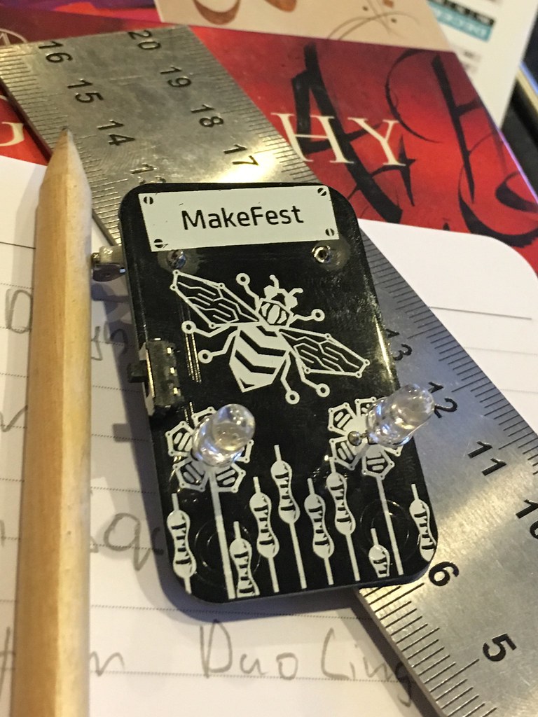
It’s a design by Andy Dutton, Mark and Angela Gilbert and Torben Steeg. H had fun soldering it together (it’s definitely not her first time, so I think she surprised the man teaching them at the museum) and the ladies that had missed out wanted to know where they could get kits for an uncoming craft session, and for various relatives they thought would like them.
Buy
As far as I can see, ‘Learn to Solder’ kits come in three forms: available in America, way too expensive to buy in bulk, and way to expensive to buy in bulk and also only available in America.
To be fair, the individual kits you can buy online are probably great for someone with a son or daughter they want to introduce to soldering, look to be of high quality, are presented well with instructions and (being put together in the West) are hardly going to be a source of vast profits for any of the people who sell them.
But faced with sourcing up to fifty of them, I was interested to see how cheaply they could be made. I’d like to apologise in advance for the fact these will not be sustainably made badges: the answer to the question “how to get something done cheaply” is “create externalities in China”.
Build
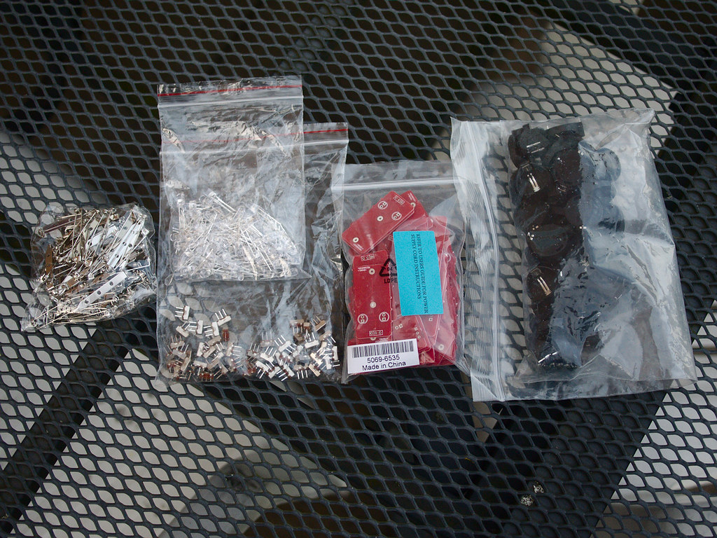
We’ll need some RGB LEDs, battery holders, switches and pin bars. So that’s £8 then.
(Like the original badge, I’m using RGB LEDs with the control circuitry to blink already built in - so that’s three colours of LED and something to make them flash for 3p each)
The remaining step and reason for this post, is the PCB.
My PiGlow to Trinket adaptor hasn’t arrived from OSH Park yet, but to get things done as cheaply as possible, I was confident I couldn’t beat the pricing at Dirty PCBs. You can get 30 5x5cm boards delivered for $28 (£20). That means our per-badge cost is 93p per badge (including components with some spares left over), but I think I can get it lower.
The PCB is the most expensive individual part of this build - but 5x5cm is actually pretty big for a badge. I could cut the cost in half by panelising the board: putting two unconnected circuits on the PCB. There used to be a warning on the Dirty PCBs site against this, but it looks like it’s not there any more, so perhaps they have a new supplier who’s even more dirty than before.
With 60 badge PCBs, I’ll have enough for 50 badges with 10 PCBs left over, still for $28 but with a per-badge cost of 56p! Including postage!
KiCad
I put together a dumb schematic with two badges that aren’t connected:

This does not work when you switch over to pcbnew - the “air wires” join grounds and common pins together in ways I didn’t want and I needed to override the design rules to make anything even half work.
Instead, I started over with a blank design straight in pcbnew, with no schematic. You need to disable design rules for this too, because you end up laying traces wherever is convenient and there are no air wires defined.
I put two 5mm LEDs down, an SPDT switch from a GitHub repository and then tried to find a suitable footprint for the CR2032 holder. Well, it turns out when you buy from the cheapest possible supplier on AliExpress - you don’t always get a datasheet. I had to look through Google Images search for something that looks close and I’ll need to hope for the best.

The easiest way to get 20mm spacing was to lay everything out on the board the way that I wanted and then change to a 5mm grid - luckily changing the grid that you’re using doesn’t cause existing things on the PCB to snap into their new best locations or the design would be a lot harder.
I laid traces manually, ran them too close to some holes and generally made things harder than I needed to. By simply deciding that the positive end of the battery holder is going to go near the anode of the LEDs I was able to get rid of all my vias and “too close to call” trace-near-hole situations and make it a one sided board. It pays to step back and rethink your design when you’re having trouble routing things.
A major advantage of using pcbnew without a schematic is that a new option becomes available in the file menu: Append board. You can effectively import another PCB into this design and have the two, unconnected, boards on the same work space. After finishing the single board, I did this and ended up with two unconnected boards: perfect.
I had to manually draw around the boards on the ‘edge cut’ layer, and make the little perforated snap lines myself - I hope these work, I haven’t tried before, and if they don’t, I’ll have 30 useless boards on my hands.
Here’s the finished board, still fitting in the dimensions I was hoping for:

And a 3D render of the same:

You can see that the drill hits and pads are much larger than usual - that’s because I haven’t used someone else’s footprint for the battery holder, and I’d like there to be at least a little wiggle room if my dimensions are off.
I threw an OSHW logo on the solder mask and an AWDB on the silkscreen - there
was so much empty space. I'll publish the gerbers and KiCad files once
I know they work - I don't want anyone wasting their time making copies of a
board that has flaws.
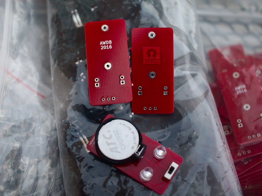
It all arrived!
The bars, battery holders and switches arrived pretty fast. Even the boards arrived fairly quickly, unfortunately the most delayed item I ordered were the LEDs themselves — arguably the most interesting bits.
The boards looked correct and the panelising that I did by hand worked fine too - they snapped right along the perforations that I had made without much force at all, but until the LEDs arrived I couldn’t be 100% sure that I hadn’t made some basic mistake with the circuit layout.
Also, there was definitely a time when I thought I’d put my name on the silkscreen backwards, because I didn’t trust the gerber viewer that I was using. Thankfully both my initials and the OSHW logo have come out the right way around.
I soldered the first badge up quickly and it all works. Not a massive surprise; it’s an amazingly basic circuit, but even basic things go wrong.
As promised, the gerbers and PCB design are on GitHub