PiGlow to Adafruit Trinket Adaptor
Over the last couple of weeks I’ve been building a flash-y LED box thing. It’s not an overly ambitious project, but it uses up some parts I had in my bin which were too nice not to use, and it let me practice my PCB and 3D design to go about building something which is more-or-less a product. Far more finished than the “shove all the wires in and screw the lid shut” approach I often favour.
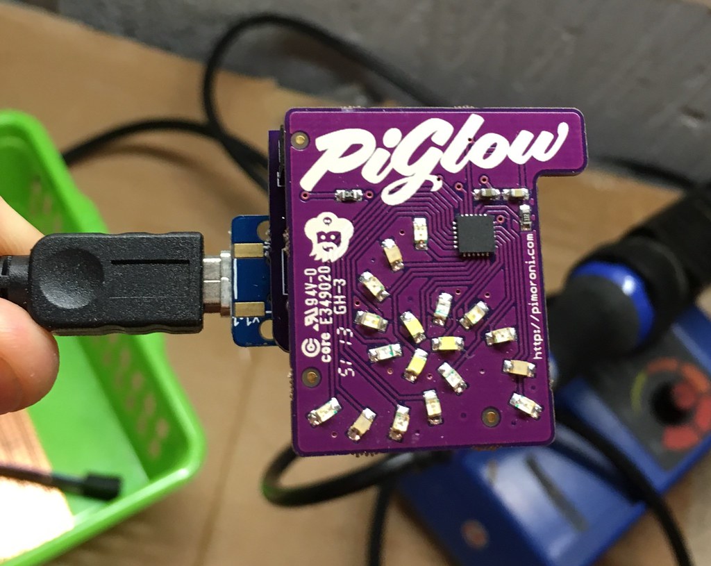
I had a 3.3V Adafruit Trinket and a Pimoroni PiGlow going spare. The GPIO on my Pi is taken up with another Pimoroni gadget, the Pibrella. I had gotten the PiGlow speaking I2C before; it was one of my first experiments with the BusPirate, so I was reasonably confident this could be made to work simply.
After a quick breadboard test to verify that my last write-up was accurate about which pins I would need, I sketched out a rough schematic. How rough?

Rough.
Even with such a simple design, having a schematic lets me verify that the PCB routing is electrically correct. This is opposed to how I did things on my badge design, where it’s effectively a “free-hand” PCB.

I wanted the project to be small for aesthetic reasons, but also because OSH Park charge by the square inch. I got things in at 1.01”, which made the design $5.05 for three boards, delivered.
About two weeks later, my Perfect Purple PCBs arrived. I grabbed some pins from work and soldered them up. This is where I learned why they give you three boards. I put the pins on the wrong side of the first board. I build the second board correctly, but realised that putting female pin headers on the underside made everything far too bulky. At least I was able to verify that the circuit worked correctly on that version.
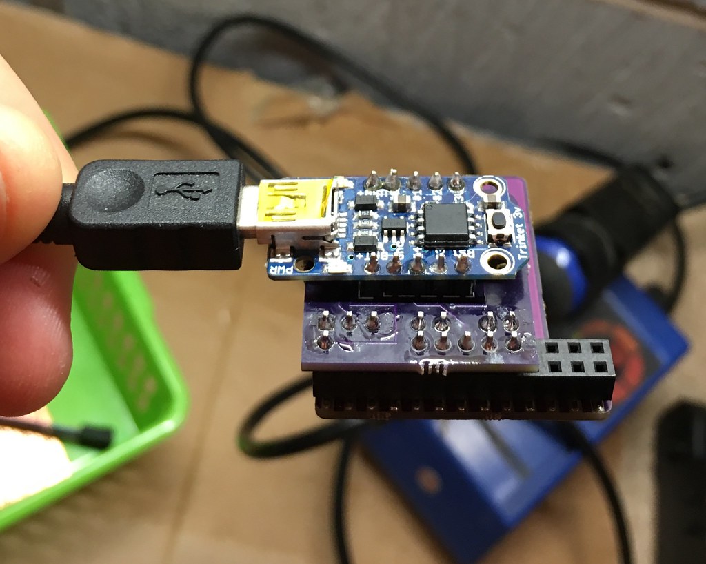
On the third attempt, I soldered the Trinket directly to the board and clipped the leads. It’s about as snug as I can make it without risking a short:
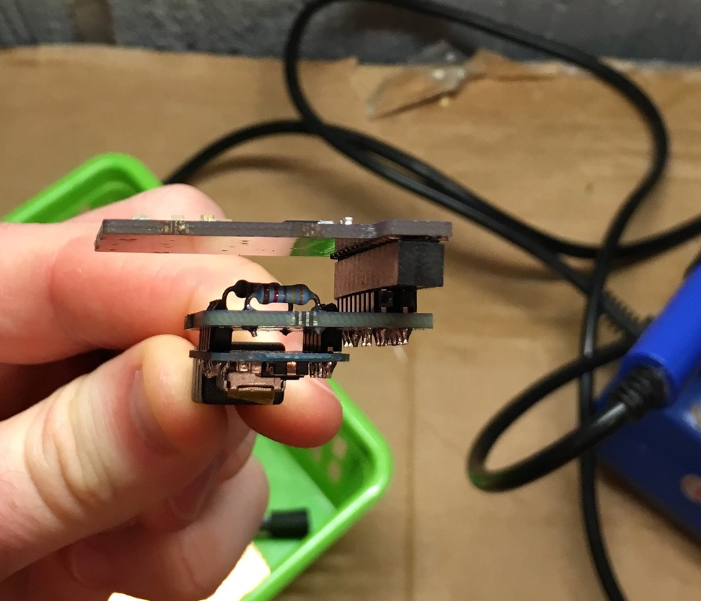
You can see where I left some of the passive pins out, rather than drilling holes for the entire header. This was to make it a bit easier to route the traces - I could make the gaps I needed by removing spare pins.
I got out my digital calipers to measure some distances, so I could start to figure out the box design. My notes:
17.5 bottom of piglow pcb to further usb connector
40x40 width of circuit board bits
6x9 cut out of usb
9x12 'pre' cut out
8 bottom of bottom pcb to further of usb
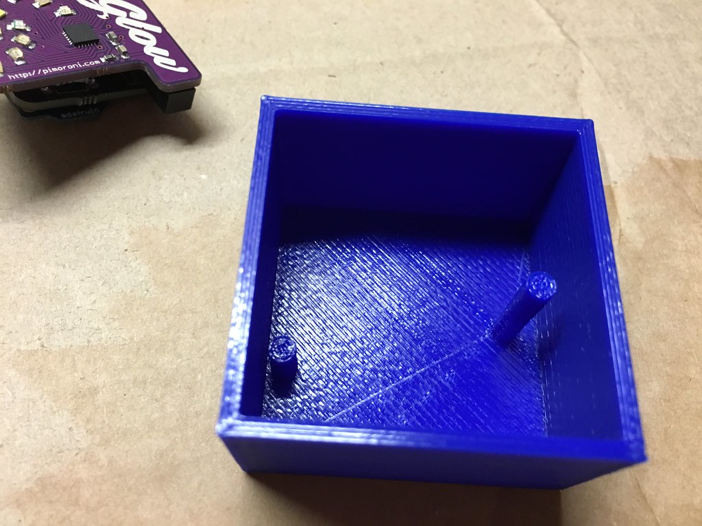
As a good European, all measurements are in millimetres. The 17.5mm is the distance from the bottom of the USB connector to the bottom of the PiGlow PCB. I measured this because I planned to have a post rise out of the bottom of the box to meet it. The 8mm from the bottom PCB to the bottom of the USB refers to my adaptor board - another post is going to rise up to match that, too.
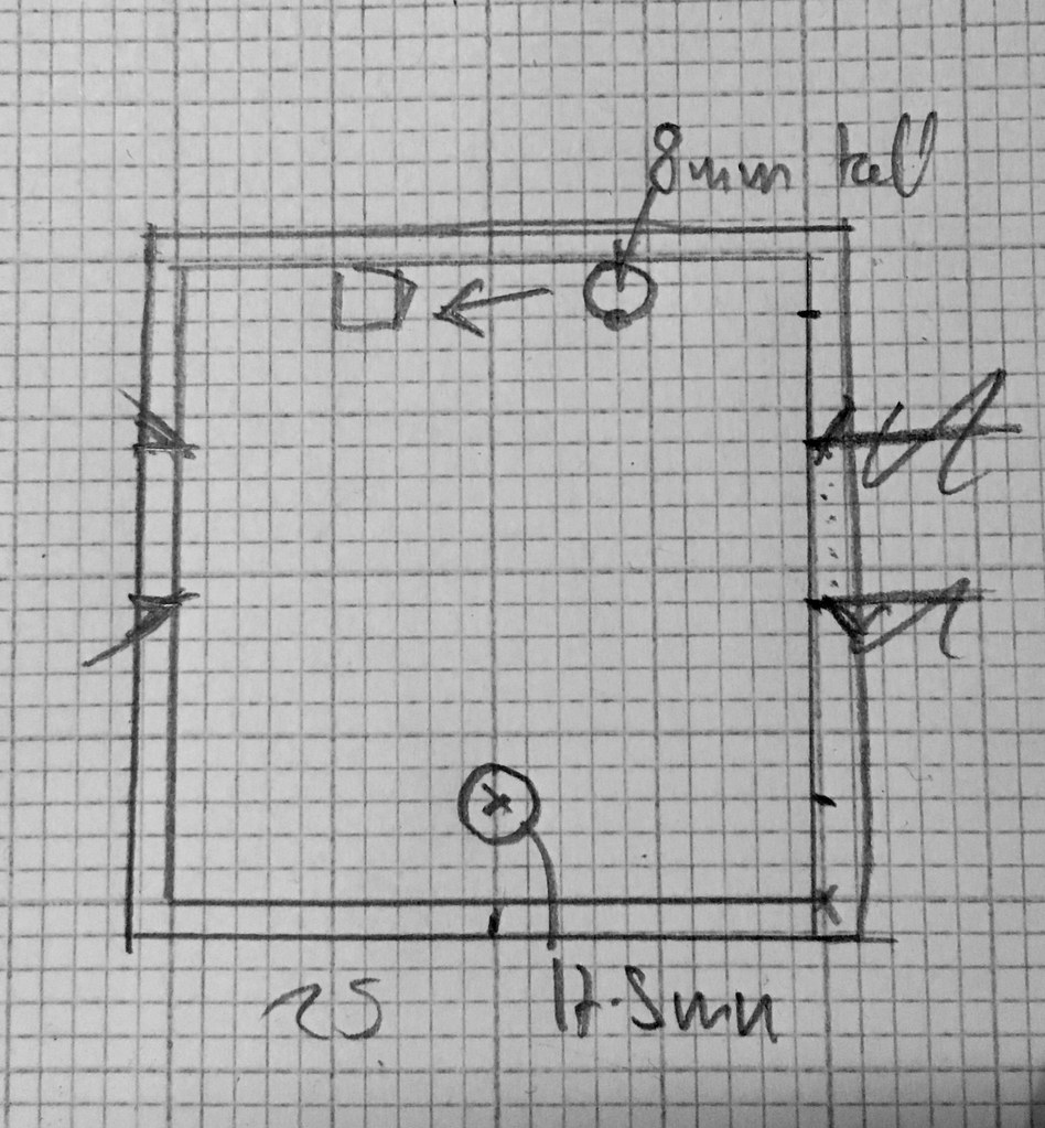
Even with some great CAD tools available, I still like to use graph paper for this stage of things. I don’t get distracted by the gap between what I think up and how to get the tools to make that happen. As you can see, I drew this backwards and had to reverse it later, but with 2mm squares I could convert this 1:1 scale drawing into Autodesk 123D reasonably easily.
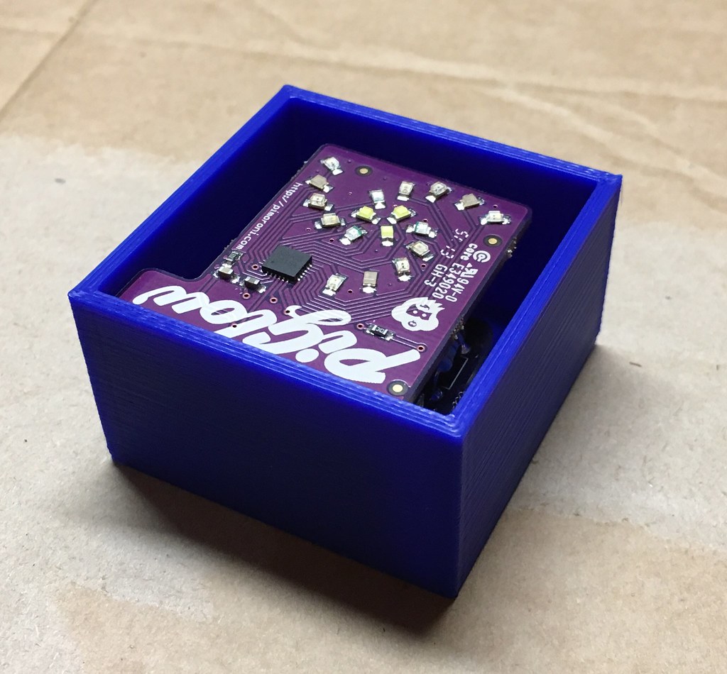
Look how it turned out! It fits snugly. Really snugly, because I forgot to put a hole in for the USB connector: whoops. Still, the two posts were a good idea and they did work first time:
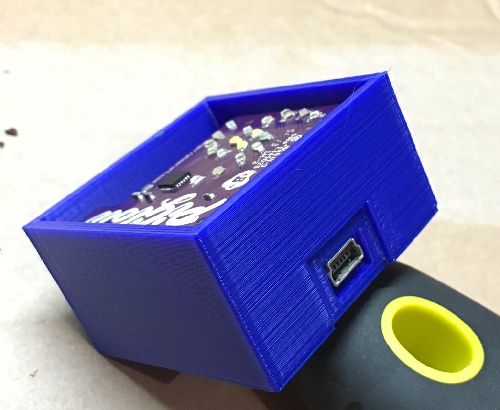
So, I actually put a USB port in, using my measurements above. The “pre cut out” is the indented area where a mini USB lead may be a bit thick and need extra clearance. That part worked well too:

(If your browser supports WebGL you can spin the box around courtesy of the GitHub STL viewer).
I used a bit of hot glue (not pictured) to fix everything in place, and it’s really firmly together. I’m genuinely pleased with this, even if it is just a box.
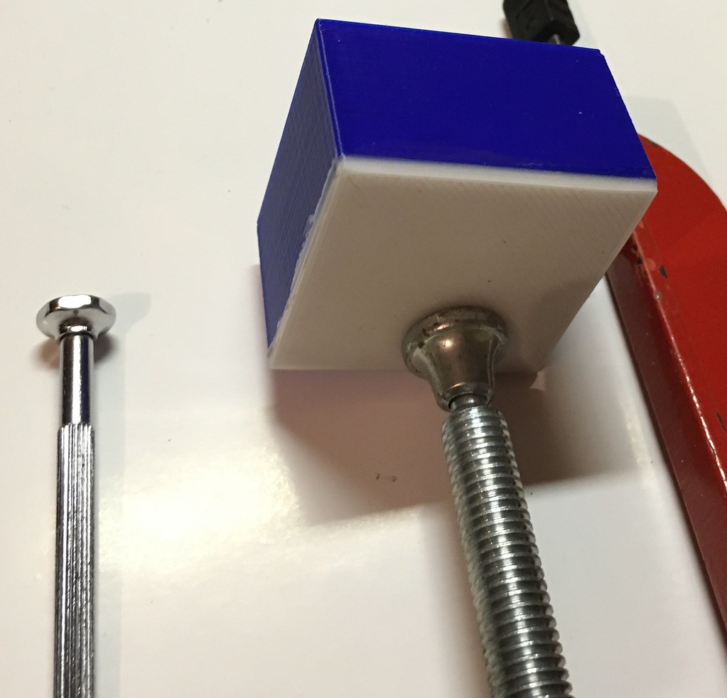
I had a lot more trouble printing the white lid to act as diffuser. I printed one with four posts which locked on to the box: that worked fine, but one of the posts broke right away. I decided that putting a lip in place would be better, but since deciding that haven’t been able to get a successful print out of my 3D printer.

The white plastic I have is all ABS and more sensitive to print, and every time I try I’ve seen curling at the edges. It looks like my first print was a fluke. So, in the interests of wrapping things up while I figure out what’s going wrong with my ABS printing, I’ve used Gorilla glue and a clamp to seal the box. I sure hope I don’t need to make any changes!
The software is the final piece. You can view it directly on GitHub — in its current form it just sets random LEDs to random brightness levels, but that’s actually pretty visually pleasing. I’ll add support for serial control at a later date, when I get bored of mesmerising lights.
The whole project can be viewed and downloaded from its GitHub repo.